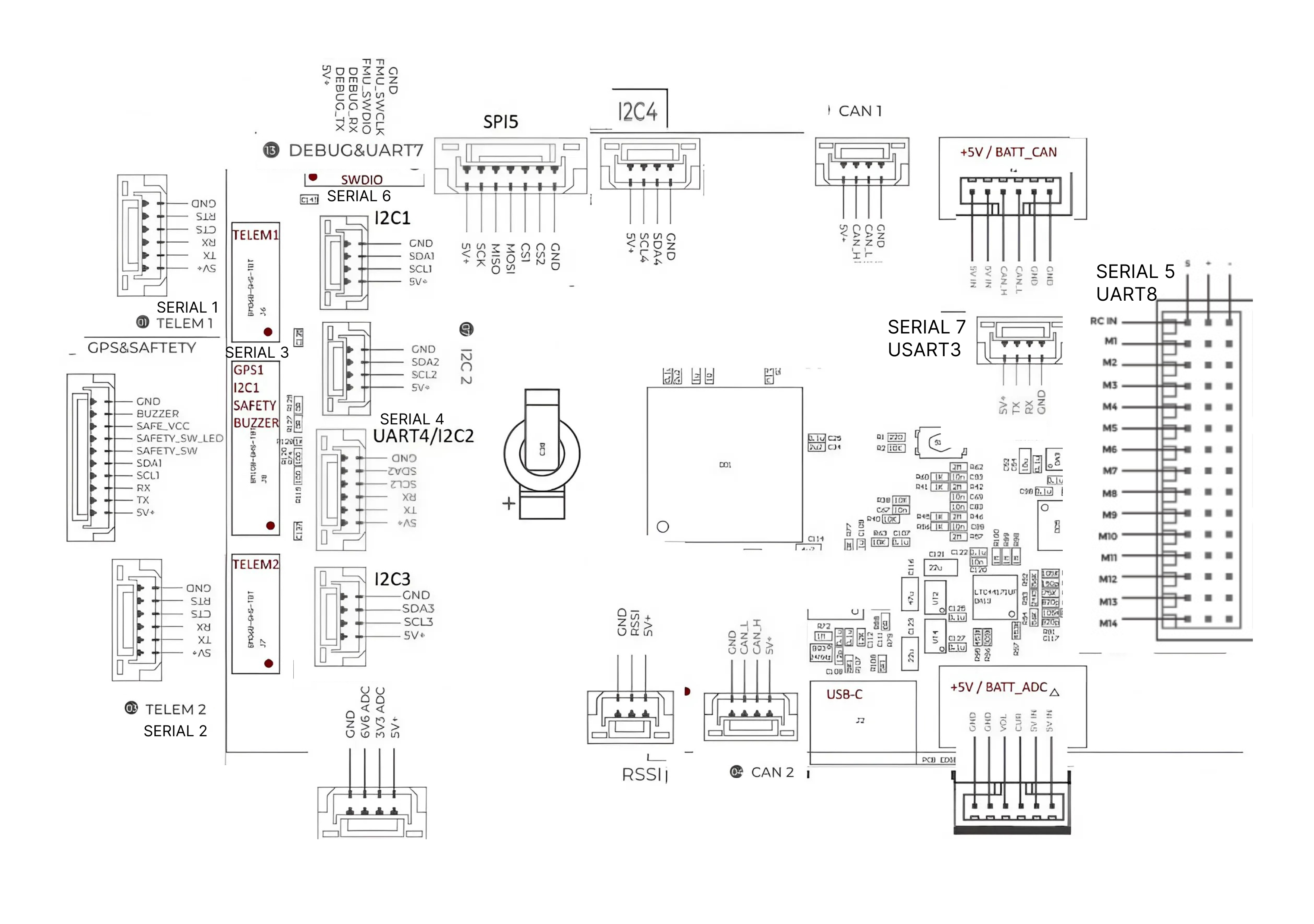
SERIAL1 and SERIAL2. Both support hardware flow control (CTS/RTS) and DMA.
Pin
Signal
Level
1
VCC
+5 V
2
TX
+3.3 V
3
RX
+3.3 V
4
CTS
+3.3 V
5
RTS
+3.3 V
6
GND
—
GPS & SAFETY — 10 pins
SERIAL3. Combined connector: GPS, the I2C1 bus, safety switch and buzzer.
Intended for GPS modules with a built-in compass, switch and buzzer.
Pin
Signal
Level
1
VCC
+5 V
2
GPS1_TX
+3.3 V
3
GPS1_RX
+3.3 V
4
I2C1_SCL
+3.3 V
5
I2C1_SDA
+3.3 V
6
SAFETY_SW
+3.3 V
7
SAFETY_SW_LED
+3.3 V
8
SAFE_VCC — not used
—
9
BUZZER
battery voltage
10
GND
—
Pin 8 (SAFE_VCC)
Brought out to the connector but not connected to anything on the board — the same as on the CUAV X7.
Power the safety switch and its LED from pin 1 (+5 V).
UART4 / I2C2 — 6 pins
SERIAL4. Combined port: a second GPS UART plus the I2C2 bus.
Pin
Signal
Level
1
VCC
+5 V
2
UART4_TX
+3.3 V
3
UART4_RX
+3.3 V
4
I2C2_SCL
+3.3 V
5
I2C2_SDA
+3.3 V
6
GND
—
TELEM3 — 4 pins
SERIAL7 (USART3). Additional telemetry port, no flow control.
Pin
Signal
Level
1
VCC
+5 V
2
TX
+3.3 V
3
RX
+3.3 V
4
GND
—
DEBUG / SWD — 6 pins
SERIAL6 (UART7) — system console, plus the SWD interface for FMU debugging.
Pin
Signal
Level
1
VCC
+5 V
2
DEBUG_TX
+3.3 V
3
DEBUG_RX
+3.3 V
4
SWDIO
+3.3 V
5
SWCLK
+3.3 V
6
GND
—
Power
POWER A — analog module, 6 pins
Pin
Signal
Level
1
VCC
+5 V
2
VCC
+5 V
3
CURRENT
up to +3.3 V
4
VOLTAGE
up to +3.3 V
5
GND
—
6
GND
—
POWER C — DroneCAN module, 6 pins
Pin
Signal
Level
1
VCC
+5 V
2
VCC
+5 V
3
CAN_H
+3.3 V
4
CAN_L
+3.3 V
5
GND
—
6
GND
—
CAN — 4 pins
CAN1 and CAN2 share the same pinout.
Pin
Signal
Level
1
VCC
+5 V
2
CAN_H
+3.3 V
3
CAN_L
+3.3 V
4
GND
—
I2C — 4 pins
Four separate connectors: I2C1, I2C2, I2C3, I2C4, all with the same pinout.
I2C1 is also present on the GPS&SAFETY connector, and I2C2 on the UART4 connector.
Pin
Signal
Level
1
VCC
+5 V
2
SCL
+3.3 V
3
SDA
+3.3 V
4
GND
—
Other connectors
ADC — 4 pins
Two spare analog inputs.
Pin
Signal
Level
1
VCC
+5 V
2
ADC 3.3 V
up to +3.3 V
3
ADC 6.6 V
up to +6.6 V
4
GND
—
RSSI — 3 pins
Pin
Signal
Level
1
VCC
+5 V
2
RSSI
up to +3.3 V
3
GND
—
SPI5 — 7 pins
External SPI bus with two chip-select lines.
Pin
Signal
Level
1
VCC
+5 V
2
SCK
+3.3 V
3
MISO
+3.3 V
4
MOSI
+3.3 V
5
CS1
+3.3 V
6
CS2
+3.3 V
7
GND
—
Servo rail
Three rows of contacts: signal, servo power and ground. Outputs are labelled M1–M14, with a separate RC IN contact for the receiver.
Contact
Function
RC IN
RC receiver input, also SERIAL5 (UART8)
M1 – M14
Outputs 1–14
Each output has three contacts: S — signal, + — servo
power, − — ground. All 14 outputs are implemented identically.
DShot
Channels 1–12 support DShot; channels 13–14 are PWM only, because their timer has no DMA.
Output grouping and the shared rate are covered in the
Configuration section.
Servo power
The controller does not supply power to the servo rail. To power servos, connect a BEC
to any plus/minus pair on outputs M1–M14. Maximum 10 V.