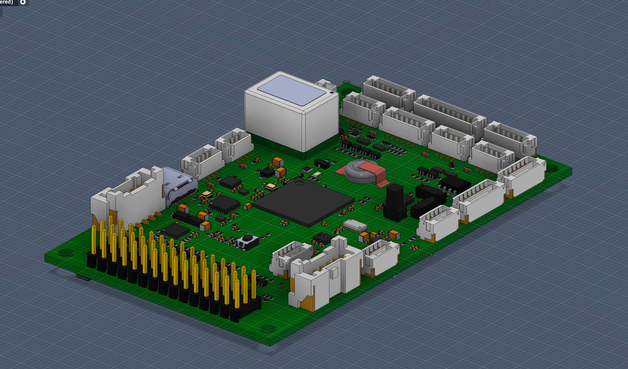
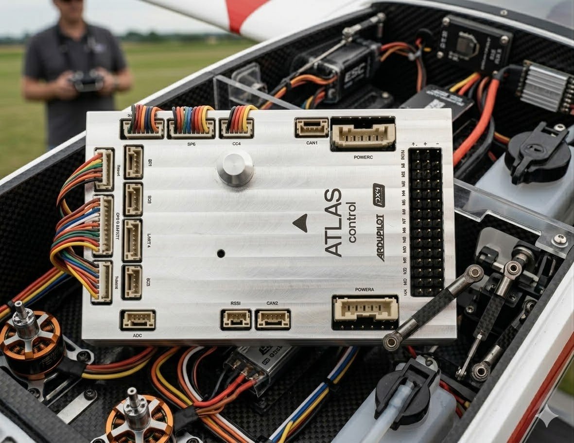
Atlas Control
Overview
Atlas Control is a Ukrainian-made flight controller built around the STM32H743XIH6 processor with industrial-grade sensors. ArduPilot compatible. Designed for academic research, commercial integration and defence applications.
Three models
All three boards are identical in connectors, power and pinout. The only difference is the primary inertial sensor on the SPI1 bus.
| Atlas Control | Atlas Control Plus | Atlas Control Pro | |
|---|---|---|---|
| Processor | STM32H743XIH6 | STM32H743XIH6 | STM32H743XIH6 |
| Primary IMU (SPI1) | ICM-42688-P | Murata SCH16T | ADIS16470 |
| Second IMU (SPI6) | ICM-42688-P | ICM-42688-P | ICM-42688-P |
| Third IMU (SPI4) | BMI088 | BMI088 | BMI088 |
| Barometer | MS5611 ×2 | MS5611 ×2 | MS5611 ×2 |
| Compass | RM3100 | RM3100 | RM3100 |
| IMU heater | yes | yes | yes |
Which model to choose
Control — the baseline, with two mutually redundant ICM-42688-P units.
Control Plus — Murata SCH16T, an industrial sensor with high stability
against vibration and temperature.
Control Pro — ADIS16470, a tactical-grade inertial module with
substantially lower gyro drift; the choice for long flights and GNSS-denied operation.Built-in sensors
| Sensor | Component | Bus | Purpose |
|---|---|---|---|
| Accelerometer / gyroscope | ICM-42688-P (Control) Murata SCH16T (Plus) ADIS16470 (Pro) | SPI1 | Primary IMU |
| Accelerometer / gyroscope | ICM-42688-P | SPI6 | High-rate, redundant |
| Accelerometer / gyroscope | BMI088 | SPI4 | Vibration-resistant, redundant |
| Magnetometer | RM3100 | SPI2 | Internal compass |
| Barometer | MS5611 ×2 | SPI4, SPI6 | Altimeter, redundant |
| Non-volatile storage | FRAM FM25V05 | SPI2 | Parameter storage |
Sensor orientation
Sensor rotation is handled in firmware. Mount the board arrow forward —
there is no need to change AHRS_ORIENTATION.Interfaces
| Interface | Count | Details |
|---|---|---|
| Serial ports | 9 | SERIAL0–SERIAL8: 7 UARTs + 2 USB |
| PWM outputs | 14 | channels 1–12 support DShot |
| RC input | 1 | SBUS / CPPM / DSM on the servo rail |
| GPS ports | 2 | GPS&SAFETY (SERIAL3) and UART4 (SERIAL4) |
| I2C | 4 | all brought out to connectors |
| CAN bus | 2 | DroneCAN |
| Power ports | 2 | Power A (analog), Power C (DroneCAN) |
| Analog inputs | 2 | 3.3 V and 6.6 V, plus a separate RSSI input |
| SPI | 1 | external SPI5 with two chip selects |
| USB | 1 | USB-C |
Also included: microSD slot, safety switch, buzzer, RGB status LED.
Power
| Parameter | Value |
|---|---|
| Main power | 4.5 – 5.4 V |
| USB input | 4.75 – 5.25 V |
| Servo rail input | 0 – 10 V |
| Dimensions | 98 × 62 × 16 mm |
| Weight | 58 g |
| Operating temperature | −20 … +85 °C |
Power redundancy
Triple redundancy is supported: POWER_A, POWER_C and USB.
Priority: POWER_A / POWER_C → USB.Warning
The servo rail is isolated: the controller does not power servos and
is not powered by them. The board must be supplied from POWER_A,
POWER_C or USB. Servo rail voltage is not measured.RCIN port
Intended only to power the RC receiver. Do not connect external power or loads to it.The board